Order Digital Reprints
Sign Me Up!
Sign up Digital!
Subscribe to Print!

Interested in Valves?
Get Valves articles, news and videos right in your inbox! Sign up now.
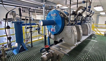
Valves + Get AlertsFor the past decade, high-speed turbo blowers have helped many wastewater treatment facilities significantly increase aeration efficiency and drive down energy costs.
At the same time, as some plants have reported blower failures causing treatment outages and discharge permit violations, some engineers and operators have come to consider the technology unreliable. In reality, the majority of treatment plants using turbo blowers have operated them successfully and enjoyed years of trouble-free service.
Why do some plants operate well with turbo blowers and others not? The answers lie in the blower design, blower operating conditions and plant environmental conditions.
Design differences
Turbo blowers are popular for their high efficiency, small footprint and low maintenance. They deliver more air per square foot, reducing aeration system installation costs and the plant’s carbon footprint. They also need minimal preventive maintenance, mainly requiring operators to simply change the air filter. All these factors contribute to low life-cycle cost.
Several design differences can affect turbo blower reliability and operating costs including the type of bearings used, how the motor is cooled, and how the blow-off safety valve is implemented.
Bearing design
In general, the largest design difference between turbo blowers lies in bearing design.
Airfoil bearing blowers are simple in design, with no bearing controllers or sensors, and its capital cost is relatively low. They work on a principle similar to journal bearings in car engines in that a viscous fluid is pumped into the clearance between the bearing housing and the rotating shaft. In this case, the viscous fluid is air, which creates a wedge that lifts the shaft off the fixed portion of the bearing. As long as the blower operates at constant pressure and constant flow, there should be no friction. Issues can arise during operation at low flow or high pressure, or in the presence of corrosive gases in the airstream or excessive heat.
Magnetic bearings have a more advanced design with electromagnetic coil packs that surround the steel shaft of the blower and motor, exerting a pull on the shaft. A high-frequency controller senses where the shaft is located relative to the desired position and adjusts power to the coil packs. If the shaft moves out of alignment, the controller sends more current to one side of the bearing to pull the shaft back into position. This allows the shaft to continuously rotate in its mass center. Provisions are made to maintain bearing levitation in case of a power failure. Magnetic bearings allow the machine to tightly control impeller clearances and provide a dynamic response to choke and surge conditions, protecting the blower and motor.
Motor cooling
Turbo blowers can use either permanent magnet or induction squirrel cage motors. Regardless of type, the motor is cooled using air or water.
Air-cooled motors can use either passive or forced air cooling. In a passive system, intake air is drawn across the motor windings before it enters the blower intake for compression. In a forced air system, intake air is drawn using an electric or shaft-mounted fan in the blower enclosure.
Air-cooled motors need proper maintenance to keep foreign particles, corrosive gasses, or rust from fouling the cooling channels, motor windings, and blower bearings.
Water-cooled motors pass water through a cooling jacket around the motor. More robust designs include a thermal-regulating valve that controls the cooling water temperature. The consistent temperature helps control thermal expansion of the motor and blower shaft, while the sensors monitor the condition of the cooling system to maintain efficiency and reliability. Effective control and monitoring reduces wear and increases the lifetime of the motor.
Blow-off valves
Blow-off valves protect centrifugal blowers against surge, which occurs when the blower cannot convert enough kinetic energy (airflow) into potential energy (pressure) to overcome the system back pressure. This can happen due to increased header pressure or decreasing flow beyond the blower minimum design speed. When surge occurs, the blower shaft moves around, potentially causing contact between the shaft and bearings. A blow-off valve vents the pressure in the package to prevent this contact.
There are different types of blow-off valves; the style of valve used is different for each manufacturer.
Solenoid blow-off valves are the most common type used in airfoil bearing blower packages. These are simple, inexpensive and readily available. However, solenoid valves don’t offer the same level of protection as other blow-off valves used in the high-speed turbo blower market.
Fast-acting blow-off valves are also used in airfoil bearing blower packages. Each time the shaft contacts the bearing, there is a risk of bearing deformation, which leads to machine failure. Airfoil bearings use special coatings that experience a small amount of wear each time the shaft contacts the bearing. Due to the delicate nature of airfoil bearings, the blow-off valve must react immediately to a surge condition. That is why fast-acting blow-off valves must fully open in milliseconds.
Modulating blow-off valves provide highly reliable service in magnetic bearing turbo blower designs. Since the magnetic bearing controller can monitor and control the blower shaft position, a fast-acting valve is not needed. When the blower controller senses that the blower is operating near a surge condition, a signal is sent to the drive to speed up and open the modulating valve. This continues until the valve is fully open or until the controller senses that the blower is no longer in surge.
Environmental conditions
There are many environmental considerations to make when installing high-speed turbo blowers in wastewater treatment plants. Poor power quality, contaminants in the atmosphere, and incorrect piping and ventilation can all result in poor reliability and performance.
Power quality
If the power supply to the blower package is of poor quality, the blower will have poor reliability. The sensitivity of high-frequency electronics used in turbo blowers can heighten the risk of poor power quality, leading to shutdowns or shorter life for motors, VFDs, tuning reactors and sine filters. Problems can arise when the supply voltage is greater or less than the VFD-rated voltage, or when there is harmonic interference from nearby pumps, blowers and nonshielded sensor cables.
Atmospheric contaminants
For reliable turbo blower operation, the surrounding environment must be free of contaminants, including particles and corrosive gases. If the blower process air intake contains hydrogen sulfide (H2S) — such as from an anaerobic digester — then the impellers, air-cooled motors, airfoil bearings, and copper in the magnetic blower bearings can experience corrosion. Cooling air intake containing H2S can corrode the blower control panel, VFD, tuning reactor, sine filter and air-cooled motor windings, ultimately leading to blower failure.
In the Northern states, piles of road salt may be stored on municipal lots near treatment plants, and salt particles can find their way into the air. Salt particles combined with water vapor will rust wetted ferrous parts and corrode wetted aluminum parts, affecting blower reliability and shortening maintenance intervals.
Metal particles from nearby smelters, forgers, recycling plants or scrapyards can shorten the life of air-cooled motors, cause pitting of blower impellers, or cause failure of airfoil bearings. In addition, metal particles in the blower cooling system can result in short-circuits when deposited on the blower control panel, VFD, tuning reactor, sine filter and air-cooled motor windings.
Piping and ventilation
Incorrect piping and ventilation of blower cooling and process air can create excess heat or pressure, reducing performance or causing failure. Process air can be drawn from inside the blower room or outside the building. When designing inlet piping and ducting, it is important to abide by the manufacturer’s recommended intake headloss. Excessive bends or elbows and sections with reduced cross-sectional area will increase pressure drop on the blower inlet.
Common ducting of multiple blower inlets — a frequent practice — causes a running blower to pull vacuum on the inlet of a nonrunning blower, creating backflow in the nonrunning machine and increasing the differential pressure of the running machine. Turbo blowers are designed to operate at a differential pressure that is the sum of intake pressure loss plus discharge pressure head. When excessive pressure drop is introduced at the blower inlet, surge will occur when the blower can no longer produce enough discharge pressure to overcome the system head.
The same issues are common with discharge piping. Excessive elbows; reduced cross-sectional areas; and poorly maintained check valves, isolation valves, and diffuser membranes can all lead to excessive piping pressure loss. When piping is incorrectly installed, system pressure can exceed the blower design point, resulting in surge and reducing the blower life.
Operating conditions
In general, high-speed turbo blowers are best suited for secondary treatment aeration. Based on your application, find the general air requirements and recommended blower technology in the table below.
| Treatment method | Air requirements | Recommended blower technology |
|---|---|---|
| Conventional activated sludge | Fixed pressure and variable flow | Airfoil or magnetic bearing |
| Aerated lagoon | Slightly varying pressure and flow | Airfoil or magnetic bearing |
| Sequencing batch reactor | Greatly varying pressure and flow | Magnetic bearing only |
| Moving bed biological reactor | High flow and variable pressure | Airfoil or magnetic bearing |
| Membrane bioreactor | Fixed pressure and variable flow with higher pressure purge condition | Airfoil or magnetic bearing with compressor for filter scour |
| Anaerobic digester | Boosting gas from slight vacuum to positive pressure | High-speed turbo blower not recommended |
Conclusion
Reliable high-speed turbo blower usage in wastewater treatment plants depends on appropriate blower package design and proper operating and environmental conditions. For the highest level of reliability and efficiency, engineers and operators should do the following:
- Make sure the blower is suited to the plant application.
- Verify that the blower package uses the correct bearings, cooling system and safety valve to be robust and durable in the application.
- Check that the installation has a good-quality power supply, is kept free from airborne contaminants, and has the proper piping and ventilation installed.
About the author
Paul Petersen is a regional sales manager for blowers and low-pressure compressors with Atlas Copco Compressors, a provider of compressors, vacuum solutions and air treatment systems. He can be reached at paul.petersen@us.atlascopco.com.